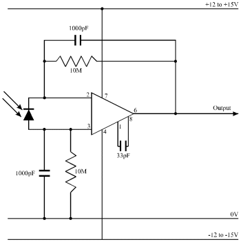
Figure A2-1 Photodiode circuit used for measurement of lamp intensity at different wavelengths.
This appendix concerns the calibration of the initial response spectrum measured for butterflies using an electroretinogram (Experiment 2-4 and Experiment 3-5) to take into consideration the intensity of the mercury lamp at different wavelengths, and to create a 'response surface' with varying wavelengths and intensities.
Firstly the intensity spectrum of the lamp was measured using a photodiode, RS stock number 305-462 (RS Electronics* ) in the light-level sensor circuit (see Figure A2-1). The lamp beam was passed through the monochromator, exactly as in the ERG experiment, and the photodiode was placed in the focused, monochromated beam. The response to flashes of light of different wavelengths from the photodiode circuit was recorded on the Lloyd Instruments PL3 chart recorder.

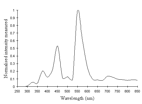
The height of the resulting peaks was measured and normalised, and plotted as a graph of photodiode response against wavelength (see Figure A2-2).
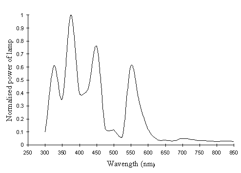
This graph then had to be adjusted for the wavelength-dependent sensitivity of the photodiode itself, as given by the manufacturer, and normalised to give the true lamp power at different wavelengths (see Figure A2-3).
The photodiode measured the power of the lamp at these wavelengths, but the actual quantum flux is what affects the visual pigments of the butterfly. The energy of the photons and hence the power is a function of the wavelength of the light, and a relative quantum flux can be obtained at a given wavelength simply by multiplying the relative power by the wavelength (in nm), and then renormalising. This produces a final graph of the relative quantum flux at each wavelength (see Figure A2-4)
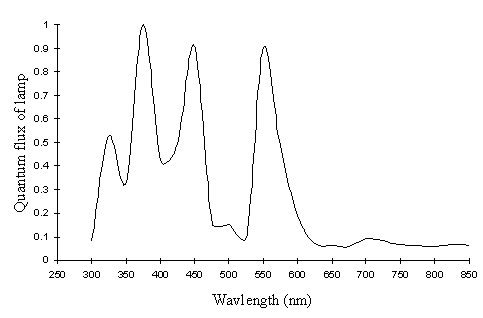
Having determined the intensity of the lamp at the different wavelengths, it was necessary to measure the intensity-response function of the butterfly at the wavelengths where the higher lamp intensity needed to be accounted for. The wavelengths which had the highest intensity were 375nm, 450nm and 550nm. These were close to the sensitivity peaks of the three main photoreception pigments found in insects (Chittka & Menzel, 1992, Backhaus & Menzel, 1992, Bennett et al., 1997, Bernard & Remington, 1991, Arikawa et al., 1987), at approximately 360nm, 460nm, and 520nm. Therefore measurements of the intensity-response function at the 375nm, 450nm, and 550nm done on several individuals were used to assess the similarity of the intensity function from different individuals.
A series of filters (Supergel swatch set, Rosco Filters**; Lee numerical swatch set, Lee Filters***) were used to achieve a range of intensities at these three wavelengths. The intensity of the light once passed through the filter was measured using the photodiode circuit, and a suitable series of filters selected for each wavelength to give a good spread of intensities (see Table A2-1 at end of Appendix for list of filters used).
The response of between three and five individual butterflies was then recorded as an ERG (for method, see Experiments 2-4 and 3-5). Unfortunately, only Papilio dardanus specimens could be obtained. However, the similarity of the response curves of Argynnis paphia and Papilio dardanus (shown in the results sections of Experiment 2-4 and 3-5 respectively) indicate that they may indeed have similar intensity-response functions, and therefore that using the intensity-response curves of Papilio dardanus to calibrate the spectral efficiency curve of Argynnis paphia may be a reasonable approximation.

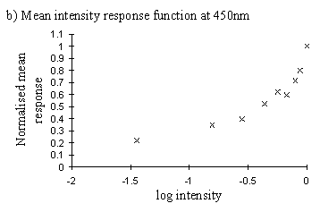
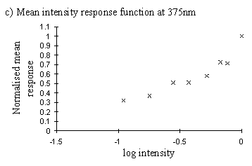
This data indicated that the intensity response functions were smooth curves (plotted on a log scale), and that data of sufficient quality could be obtained to predict the curve with reasonable accuracy from the data of one individual. This was important, as different individuals are inevitably illuminated to different degrees due to their placement in the light beam, and thus each would give slightly shifted intensity functions. Therefore data from several individuals cannot be combined.
Therefore one individual was used, and about 6 measurements of the response were taken for both the full and filtered intensity in each case. The graphs show the ratio of the mean value of the response to the filtered intensity to the mean value of the response to the unfiltered intensity as measured immediately prior to it.
The functions obtained from a single individual were mostly relatively smooth curves (see Figure A2-6), and the function:

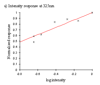
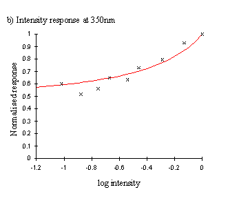
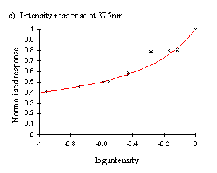
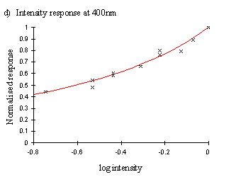
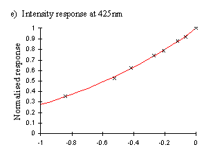

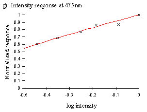
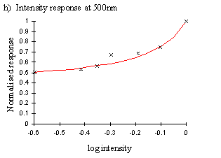
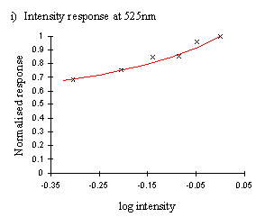
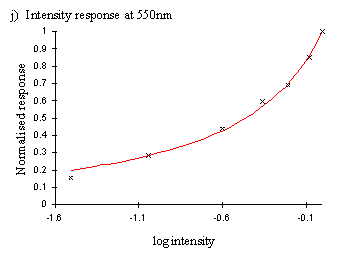
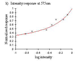

Therefore, a corrected response figure was calculated for each wavelength for which the intensity was higher than the minimum for both species, giving corrected spectral efficiency functions (shown in Figure A2-7).
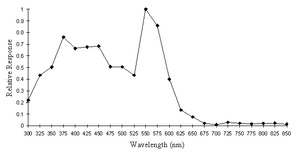
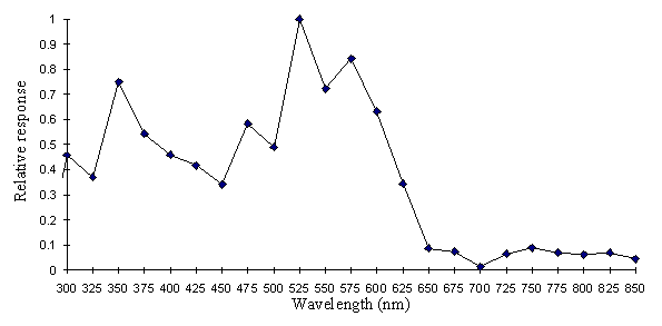
Figure A2-6, however, demonstrates how the spectral efficiency function may vary depending on the intensity at which it is measured. Therefore a more useful representation of the visual spectrum of a butterfly would be represented as a surface, taking into account both wavelength and intensity. Surfaces were therefore plotted for Papilio dardanus representing both the raw data, and a surface composed of the smoothed intensity functions shown in Figure A2-6. These surfaces are shown in the results of Experiment 3-5.
| Filter | Relative log intensity at wavelength (nm) (uncalibrated for photodiode sensitivity): | |||||||||||
|---|---|---|---|---|---|---|---|---|---|---|---|---|
| Number | 325 | 350 | 375 | 400 | 425 | 450 | 475 | 500 | 525 | 550 | 575 | 600 |
| Rosco 00 | -0.153 | -0.129 | ||||||||||
| Rosco 052 | -0.643 | |||||||||||
| Rosco 053 | -0.404 | |||||||||||
| Rosco 054 | -0.414 | |||||||||||
| Rosco 372 | -0.425 | |||||||||||
| Rosco 373 | -0.276 | |||||||||||
| Lee 002 | -1.878 | -0.365 | -0.172 | -0.253 | -0.416 | -0.823 | -0.368 | |||||
| Lee 003 | -0.378 | -0.089 | -1.04 | -0.139 | ||||||||
| Lee 004 | -0.833 | |||||||||||
| Lee 007 | -0.186 | -0.085 | -0.059 | -0.051 | ||||||||
| Lee 008 | -0.841 | -1.021 | ||||||||||
| Lee 009 | -0.753 | -0.429 | -0.435 | -0.419 | -0.428 | -0.297 | -0.073 | |||||
| Lee 013 | -1.020 | -0.554 | -0.530 | -0.524 | -0.553 | -0.537 | -0.170 | |||||
| Lee 015 | -0.206 | -0.081 | -0.074 | |||||||||
| Lee 017 | -1.447 | -0.708 | ||||||||||
| Lee 021 | -0.380 | |||||||||||
| Lee 022 | -0.352 | |||||||||||
| Lee 024 | -1.160 | -0.939 | ||||||||||
| Lee 025 | -1.040 | |||||||||||
| Lee 035 | -0.271 | |||||||||||
| Lee 036 | -0.556 | -0.411 | ||||||||||
| Lee 039 | -0.644 | -0.288 | -0.189 | -0.286 | ||||||||
| Lee 048 | -0.361 | -0.443 | -1.507 | |||||||||
| Lee 052 | -0.136 | -0.520 | ||||||||||
| Lee 053 | -0.370 | -0.172 | -0.126 | -0.118 | -0.098 | -0.276 | ||||||
| Lee 055 | -0.258 | |||||||||||
| Lee 058 | -0.957 | -0.249 | -0.355 | |||||||||
| Lee 061 | -0.480 | -0.059 | -0.245 | |||||||||
| Lee 063 | -0.065 | -0.077 | -0.331 | |||||||||
| Lee 068 | -0.352 | |||||||||||
| Lee 071 | -0.699 | |||||||||||
| Lee 075 | -0.219 | |||||||||||
| Lee 079 | -0.745 | |||||||||||
| Lee 088 | -0.155 | |||||||||||
| Lee 089 | -0.357 | -0.666 | ||||||||||
| Lee 100 | -1.092 | |||||||||||
| Lee 102 | -0.528 | |||||||||||
| Lee 104 | -0.046 | |||||||||||
| Lee 105 | -0.147 | |||||||||||
| Lee 107 | -0.576 | -0.286 | -0.598 | |||||||||
| Lee 109 | -0.746 | -0.311 | -0.271 | -0.286 | -0.115 | |||||||
| Lee 111 | -0.264 | |||||||||||
| Lee 116 | -1.047 | |||||||||||
| Lee 130 | -0.563 | -0.214 | -0.115 | -0.071 | -0.068 | -0.065 | -0.048 | |||||
| Lee 131 | -0.204 | |||||||||||
| Lee 134 | -0.598 | -0.359 | -0.242 | |||||||||
| Lee 135 | -0.696 | |||||||||||
| Lee 136 | -0.671 | -0.365 | ||||||||||
| Lee 137 | -0.681 | |||||||||||
| Lee 151 | -0.273 | |||||||||||
| Lee 153 | -0.432 | |||||||||||
| Lee 154 | -0.542 | -0.284 | -0.224 | -0.209 | ||||||||
| Lee 162 | -0.256 | |||||||||||
| Lee 169 | -0.256 | |||||||||||
| Lee 170 | -0.301 | |||||||||||
| Lee 198 | -0.805 | |||||||||||
| Lee 209 | -0.589 | |||||||||||
| Lee 241 | -0.625 | |||||||||||
| Lee 242 | -0.453 | |||||||||||
| Lee 244 | -0.118 | |||||||||||
| Lee 246 | -0.461 | -0.245 | -0.082 | -0.076 | -0.095 | |||||||
| Lee 279 | -0.126 | |||||||||||
|
Please cite this thesis as: Freeman, ALJ; 1998; D.Phil thesis, Oxford University. |
E-mail to Alexandra Freeman Back to Table of Contents Back to Home Page |